You're often making foundation decisions while the architectural scope is still moving. The wall thickness may still be under discussion. The finish schedule may still say “TBD.” The civil set may not fully resolve drainage yet. That's exactly when concrete block foundation design needs the most discipline.
A CMU foundation is forgiving in some ways and unforgiving in the ones that matter most. It can accommodate reinforcement, grout, insulation, and straightforward sequencing on site. But if the wall is under-designed for backfill, if the drainage plane is incomplete, or if moisture migration is ignored because “the basement looks dry enough,” the problems don't stay in the foundation. They show up in framing movement, cracked finishes, wet insulation, stained flooring, and callbacks that should never have happened.
Most guides stop at the wall section. They don't connect structural design to finish performance. That's a mistake, especially when the project includes premium materials like handmade cement tile. The foundation assembly and the interior finish package aren't separate conversations. They're the same assembly viewed from different trades.
Why Flawless Foundation Design Is Non-Negotiable
A foundation wall doesn't get the benefit of a graceful failure. When it's wrong, the consequences usually spread upward and outward. The structure bears on it, the site drains toward or away from it, and every below-grade finish depends on it staying stable and dry.
That's one reason CMU became such a dominant foundation material early in modern construction. The modern concrete block industry began in 1899, when Harmon S. Palmer patented a cast iron block machine. By 1915, nearly 75% of all concrete blocks manufactured in the United States were used for foundation and basement walls, replacing older materials like stone and timber (historical reference). The trade adopted CMU at scale because it solved real jobsite problems: speed, repeatability, and workable structural capacity.
Where projects usually go off track
The bad outcomes aren't mysterious. They usually come from one of these decisions:
- The wall was treated like generic masonry: The designer sized it from habit instead of from actual soil and structural loading.
- Drainage was deferred to the field: The wall ended up resisting water pressure it was never meant to carry continuously.
- Reinforcement was value-engineered too aggressively: The assembly looked acceptable until the first real seasonal cycle.
- The finish team inherited a wet substrate: Tile, flooring, and trim became the first visible signs of a foundation problem.
Practical rule: If a drawing set treats the foundation as a standard detail instead of a site-specific structural system, expect expensive corrections later.
Good concrete block foundation design is less about finding a clever section and more about controlling interfaces. Soil to footing. Footing to wall. Wall to waterproofing. Wall to slab. Slab to finish. If one interface is weak, the rest of the system starts compensating for it.
Starting with the Ground Up Site Assessment and Soil Analysis
The first real design decision isn't block size or rebar layout. It's whether the team has enough information about the soil to design responsibly. Without that, footing dimensions, drainage strategy, and wall reinforcement are all based on assumption.

What the geotechnical report needs to settle
A geotechnical report isn't paperwork. It's the document that tells the structural designer what the ground will tolerate and what the water will do over time. On a CMU foundation, that affects nearly every line on the detail sheet.
I want the report to answer a few practical questions clearly:
- Bearing behavior: Can the native soil support the footing without unacceptable settlement?
- Water conditions: Is there a perched water condition, a high water table, or a seasonal saturation issue?
- Soil character: Does the backfill and native soil hold water, drain freely, expand, or freeze aggressively?
- Excavation stability: Will the excavation stay clean enough to place and inspect the footing properly?
If any of those remain vague, the “cost savings” of skipping a proper review usually disappear in redesign, overbuilding, or remediation.
Read the site, not just the report
Field observation still matters. A dry site visit in one season doesn't prove the site stays dry. Cut slopes, neighboring grade, roof runoff paths, hardscape levels, and retaining conditions all affect how a below-grade CMU wall performs.
Watch for these red flags before finalizing the foundation approach:
| Site condition | Why it matters for CMU |
|---|---|
| Upslope runoff toward the building | Increases hydrostatic exposure and drainage demand |
| Poor surface grading near the perimeter | Keeps water against the wall instead of moving it away |
| Dense or slow-draining soil | Raises the importance of drainage stone, filter fabric, and collection piping |
| Adjacent hardscape at high elevation | Can trap water near the top of wall and at entries |
| Interior finish expectations below grade | Tightens moisture control tolerances significantly |
When the interior scope includes sensitive finishes, the team should coordinate the substrate strategy early. A useful reference for that side of the assembly is this guide to moisture barriers over subfloors, especially when the foundation and slab need to support low-permeability or moisture-sensitive finish layers.
Site preparation affects wall performance
Designers sometimes separate grading from structure too sharply. On actual projects, the grading plan can determine whether a CMU wall behaves like a dry structural enclosure or a damp retaining element.
That means the site package needs to do more than meet minimum slope intent. It should direct roof water away, avoid trapping runoff at corners, and keep finished grade from burying vulnerable transitions. A clean footing trench and controlled backfill sequence matter just as much. If the contractor places poor backfill or compacts carelessly against green masonry, the wall pays for it later.
A short field refresher can help align the team on sequencing and inspection priorities:
Don't ask a foundation wall to solve a site drainage problem. Fix the site first, then detail the wall for the remaining exposure.
Calculating Loads and Sizing Footings
Foundation design gets cleaner when the load path is explicit. The footing carries building loads into the soil. The wall carries vertical load from above and lateral load from soil and water at the side. If those actions are mixed together loosely, the detailing gets sloppy and the wall thickness usually gets chosen by habit.

Separate the load types before you size anything
For a below-grade CMU wall, I break the problem into three buckets:
- Dead load from the permanent building structure.
- Live load from occupancy and use.
- Lateral load from soil backfill and, where applicable, water pressure.
That sounds basic, but many foundation mistakes come from treating the wall like it only carries gravity. In reality, the wall often behaves more like a restrained retaining element than a simple basement enclosure.
Footing sizing starts with the ground, not the wall
The footing width and depth need to reflect the bearing condition the geotechnical review supports. Structurally, the objective is straightforward: spread the vertical load enough that the soil can carry it without settlement or rotation that the structure can't tolerate.
A practical sequence looks like this:
- Establish the vertical reaction coming down from the superstructure.
- Confirm the bearing condition at the founding elevation.
- Size the continuous footing so the contact stress stays within what the soil can support.
- Check eccentricity and alignment so the wall load bears where the footing can carry it efficiently.
- Coordinate wall thickness with footing projection so masonry placement and waterproofing remain buildable.
What doesn't work is picking a standard footing width from an old house detail and hoping the wall section can absorb the mismatch.
CMU walls need a slenderness check
Advanced concrete block foundation design can't stop at gravity and bearing. A critical step is the moment magnifier calculation used to account for slenderness effects. The resulting axial load and magnified moment are then plotted on an interaction diagram, and professional benchmarks accept designs that fall within plus or minus 5% of the curve to confirm the wall section is adequate.
That check matters because a wall that looks fine under nominal loading can become marginal once unbraced height and bending amplification are considered. Residential work especially tends to underappreciate this. Designers often assume the wall is “short enough” without running the actual geometry and support conditions.
A basement wall can be thick enough to look safe and still be under-designed once backfill, unbraced height, and axial load interact.
A practical review workflow
I've found that footing and wall design goes much smoother when the team reviews it in this order:
| Review item | Primary question |
|---|---|
| Superstructure reactions | What is the footing actually supporting? |
| Founding soil | What can the soil reliably carry at this elevation? |
| Backfill condition | How much lateral demand will the wall see in service? |
| Unbraced height | How much bending amplification is likely? |
| Reinforcement concept | Is the intended wall section buildable and inspectable? |
That sequence keeps the design rooted in actual demand instead of precedent.
Don't ignore constructability in the engineering phase
A foundation can work on paper and still create trouble in the field. If the footing is too narrow for the wall, projecting membrane, drainage board, and working room all at once, execution degrades fast. The mason starts compensating. The waterproofing installer loses continuity. The inspection becomes harder because the assembly is crowded.
For that reason, I prefer details that give each trade enough physical room to do the work properly. The wall should sit on a footing that supports structural demand and leaves realistic tolerance for alignment, reinforcement placement, grout, waterproofing, and drainage components. Good engineering doesn't end with a passing calculation. It ends with a section the field can build without compromise.
Designing the CMU Wall Reinforcement and Thickness
Wall thickness and reinforcement have to be selected together. Treating them as separate decisions is how teams end up with walls that are bulky but weak in the wrong way, or reinforced heavily enough to be expensive but still poorly detailed.

Thickness is a response to demand, not a default
An 8-inch wall, a 10-inch wall, and a 12-inch wall don't just represent increasing strength. They change stiffness, grout volume, reinforcement placement tolerance, and how forgiving the wall is during construction. The right choice depends on backfill height, support conditions, openings, surcharge, and the reinforcement pattern the crew can execute consistently.
In practice, I want the selected wall thickness to do three things well:
- carry the calculated combined axial and bending demand
- allow reinforcement and grout placement without congestion
- leave enough tolerance for clean construction at corners, steps, and penetrations
If one of those three fails, the section needs revision.
Reinforcement is doing more than one job
Vertical steel is the backbone of most loaded CMU foundation walls. It helps the wall resist lateral bending from backfill and ties the grouted cells into a stronger structural unit. Horizontal reinforcement and bond beams add continuity, help distribute localized stresses, and improve performance at the top of wall and around openings.
The hollow nature of CMU is an advantage only when it's used correctly. Hollow cells make it possible to place rebar and grout strategically. They also create weak points if the design assumes reinforcement and the field omits or poorly installs it.
A useful parallel on the enclosure side is the discussion around insulating Florida homes' concrete blocks. Once you start layering structural, thermal, and moisture functions onto block construction, details have to be coordinated instead of treated as isolated line items.
The rebar necessity paradox is real
Professional judgment is essential. A low garden wall and a residential foundation wall aren't the same problem, even if both are built from CMU. But the market often treats reinforcement as a binary question: always reinforce, or save money and skip it.
That's not how actual risk behaves.
A 2025 NCMA study found that 42% of DIY and light-commercial CMU projects omitted rebar for cost reasons, and those projects had a 28% higher rate of lateral cracking after the first winter freeze compared to reinforced counterparts (Green Building Advisor reference). That's a useful warning because it shows what many field professionals already know. The loads that hurt lightly reinforced masonry often arrive seasonally, through freeze action, hydrostatic pressure, and restrained soil movement, not through obvious immediate overloading.
Field judgment: The question isn't “Can this wall stand today without rebar?” It's “Will this wall survive wet soil, freeze cycles, and imperfect drainage for years?”
A practical risk screen for reinforcement
When I'm reviewing a CMU wall concept, these conditions push the design firmly toward reinforced construction:
- Backfill against the wall: Once the wall retains soil, reinforcement stops being optional in any practical sense.
- Moisture exposure risk: Wet soil raises lateral demand and often turns small detailing errors into structural problems.
- Frost-prone region: Seasonal movement punishes under-reinforced masonry.
- Heavy load above or nearby surcharge: Additions, vehicle loads, and concentrated reactions change the wall behavior quickly.
- Openings and steps in the wall: Geometry discontinuities need continuity steel and better local control.
A wall can be modest in height and still deserve substantial reinforcement if the site conditions are unfavorable.
What doesn't work on site
Several recurring failures show up in construction photos and forensic reviews:
| Problem | Likely result |
|---|---|
| Bars placed off-location | Reduced structural capacity where demand is highest |
| Incomplete grout consolidation | Voids around steel and poor composite action |
| Mortar joints applied unevenly | More leakage paths and inconsistent wall behavior |
| Reinforcement omitted at critical cells | Cracking near corners, openings, or high-pressure zones |
The best CMU foundation walls are not just engineered well. They're detailed so the mason, inspector, and waterproofing contractor can all verify the intended assembly without guessing.
Integrating Drainage and Waterproofing Systems
A strong wall that stays wet is still a failing foundation. Moisture management has to be designed as part of the structural system because water changes the loading condition and the service life at the same time.
Dampproofing and waterproofing are not interchangeable
Design teams blur these terms constantly. They shouldn't.
Dampproofing is a basic moisture-resistant treatment. It's appropriate where the exposure is limited and hydrostatic pressure isn't expected to build. Waterproofing is a more effective barrier system intended to resist sustained moisture and pressure conditions against the below-grade wall.
That distinction matters because CMU has joints, cells, and interfaces that are less forgiving than monolithic concrete when site water is poorly managed. If the wall sits in a condition that can hold water, a light coating won't fix the problem.

The foundation should have a complete water-management path
I prefer a belt-and-suspenders approach. Not because every site is extreme, but because below-grade repairs are expensive and disruptive.
A reliable assembly typically includes:
- Exterior membrane continuity: The wall needs a continuous protective layer, especially at transitions, laps, and terminations.
- Drainage collection at the base: Perforated pipe, clean drainage stone, and filter fabric help remove water before pressure builds.
- Surface water control: Roof runoff and grade need to send water away from the building envelope.
- Protection of penetrations and joints: Utility entries, cold joints, and changes in geometry deserve dedicated detailing.
- Buildable sequencing: The drainage system must still function after backfill, not just on the detail sheet.
For designers working through wall-side moisture control details, this overview of concrete wall waterproofing methods is a useful companion reference.
Moisture problems usually start with an incomplete system
One missing component can undermine the rest. A membrane without drainage can end up carrying too much hydrostatic burden. A drain without proper stone and fabric can clog. Good grading can still be defeated by concentrated roof discharge near a corner.
Water rarely enters a foundation because one product failed. It usually enters because the assembly lacked a complete route for control, collection, and discharge.
The review checklist I actually care about
Before approving the below-grade assembly, I look for these issues specifically:
- Is water being directed away at the surface?
- Can the wall shed and survive incidental moisture at the face?
- Can collected water move down to the drainage layer?
- Can the perimeter system discharge without backing up?
- Are the transitions at slab edge, footing step, and penetrations fully detailed?
If those answers aren't clear in the drawings, the contractor will fill in the blanks in the field. That's rarely where you want design decisions made.
Adapting Designs for Climate and Code
A standard CMU foundation detail doesn't travel well. Climate and code requirements change what “adequate” means, sometimes dramatically. A wall that performs well in a mild, dry region may fail quickly in a frost-prone or seismic area if the same assumptions are carried over.
Frost regions demand depth and moisture discipline
In cold climates, the key issue isn't just low temperature. It's frost action in moisture-bearing soil. Footings need to sit at an elevation that avoids frost-related movement, and the surrounding assembly has to reduce the chance that water remains in the soils most likely to expand.
That changes both structural and enclosure detailing:
- footing elevation becomes more critical
- drainage quality matters more
- backfill selection carries more weight
- insulation strategy can become part of foundation performance
If the wall is lightly reinforced, even modest seasonal movement can telegraph into cracking or leakage paths.
Seismic regions prioritize continuity and connections
In seismic work, continuity is the issue. The wall needs reinforcing and connection details that help it behave as a tied system instead of a stack of strong but poorly connected parts. Bond beams, anchorages, and load-path continuity to the framing above become central.
A useful side-by-side comparison looks like this:
| Condition | Primary concern | Design emphasis |
|---|---|---|
| Deep frost climate | Soil movement and seasonal pressure | Footing depth, drainage, moisture control, frost-sensitive detailing |
| Seismic zone | Lateral movement and connection integrity | Reinforcement continuity, anchorage, bond beams, load path |
| Wet non-frost climate | Persistent moisture exposure | Waterproofing, drainage, capillary control, finish compatibility |
Code compliance is local for a reason
Architects and builders sometimes want a reusable “good foundation detail.” I understand the impulse, but local code amendments, geotechnical conditions, and jurisdictional expectations make that unreliable. The foundation should respond to the place, not just to the plan set.
That's especially true around:
- sill anchorage requirements
- reinforcement detailing
- opening reinforcement and lintels
- bond beam locations
- drainage expectations
- insulation and energy-code interfaces
Bond beams and openings deserve more attention than they get
Many problematic CMU walls don't fail in the middle of a clean uninterrupted run. They fail at changes in geometry. Window wells, service penetrations, stepped footings, garage stem conditions, and partial backfill conditions all create localized stress and detailing complexity.
The most dangerous detail in a foundation set is often the one copied from a typical section and applied to a non-typical condition.
A bond beam at the top of wall often does more than satisfy a structural note. It helps unify the wall, supports anchorage strategy, and improves performance where framing bears unevenly. Lintels and reinforced opening details do the same around discontinuities. These aren't decorative refinements. They're what make the wall act like a coherent structural assembly under real regional demands.
Detailing Connections and Ensuring Finish Compatibility
Many otherwise competent foundation packages frequently fall short. The structure works. The drainage might even work. But the interface between the foundation and the interior finish scope hasn't been thought through carefully enough.
That gap matters because the below-grade CMU assembly can affect flooring and wall finishes long after the structural inspection passes.
The top-of-wall and slab interfaces have to be deliberate
The sill plate connection, anchor layout, and air sealing strategy all need to work together. If the top of wall is uneven, if anchors interfere with framing alignment, or if the air barrier transition is left vague, the enclosure starts with avoidable weaknesses.
I also look closely at the slab edge and wall-to-slab relationship. Capillary movement, thermal bridging, and vapor movement all concentrate there. If the design team only specifies a generic vapor barrier and assumes the problem is solved, they're simplifying a multi-part moisture path into a single product decision.
Finish compatibility is a foundation issue
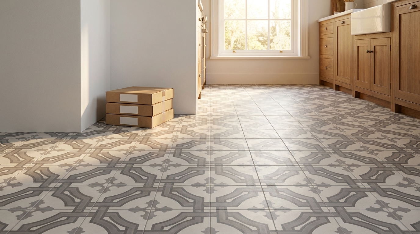
AIA data indicates that 34% of residential flooring failures in new builds from 2024 to 2025 stem from moisture migration through porous concrete masonry units that wasn't accounted for in the original design, especially when paired with non-fired, cement-based flooring like handmade cement tile (foundation moisture migration reference).
That finding aligns with what many builders and finish installers see in the field. The floor may not show liquid water. The room may not feel damp. But moisture can still move through a CMU-based assembly slowly enough to escape early notice and steadily enough to damage sensitive materials.
A workable CMU-to-finish moisture matrix
When the interior includes moisture-sensitive cement-based finishes, I want the team to review the assembly using this matrix:
| Assembly zone | Design priority | Common mistake |
|---|---|---|
| Exterior face of CMU | Limit water entry and pressure | Treating coating as the whole drainage plan |
| CMU cores and joints | Control pathways for migration | Assuming dry appearance means low moisture activity |
| Slab and wall intersection | Interrupt capillary and vapor transfer | Leaving the transition generic in the details |
| Setting substrate for finish | Provide a stable, dry receiving surface | Installing finish over a slab that hasn't been evaluated as part of the wall system |
That matrix shifts the conversation from “Do we have a vapor barrier?” to “How does moisture move through this whole assembly, and where are we stopping it?”
Practical steps that prevent premium finish failures
For projects with handmade cement tile or similar finish materials, these decisions have the biggest impact:
- Coordinate below-grade waterproofing with interior finish selection early: Don't wait for the tile schedule to force the moisture discussion.
- Detail the slab-to-wall transition explicitly: This is often where vague drawings create real-world staining, efflorescence, or bond loss.
- Require a dry, verified receiving substrate: Moisture-sensitive finishes need substrate discipline, not optimism.
- Avoid trapping moisture between low-permeability layers: Assemblies need a coherent drying strategy, not just more layers.
- Clarify responsibility across trades: Structural, waterproofing, concrete, and finish teams should understand the same moisture-control intent.
For teams refining the finish build-up over a concrete assembly, this guide on how to install a subfloor over concrete is worth reviewing during coordination, especially when the finish package is less forgiving of residual moisture.
Premium flooring doesn't fail because it's delicate. It fails because the assembly beneath it was designed as if finish performance and foundation performance were unrelated.
The best concrete block foundation design isn't only structurally competent. It anticipates what the architect wants the occupied space to become, then protects that outcome from below grade upward.
If your project includes handmade cement tile, bring the finish team into the foundation conversation early. Original Mission Tile provides design guidance, installation resources, and technical support that help architects, designers, and builders align substrate preparation with the performance demands of heritage-style cement tile.